Internally Routing Counter Signals In Labview
Di: Stella
You would have to configure a 2nd counter to count the rollover occurrences (an edge count task will by default emit a pulse on the counter output terminal when it rolls over) 12. Dynamic Trigger Route Creation With Implicit Declaration Many other drivers that Pulse Train Continuos are commonly used like NI-DMM, NI-RFSA, NI-RFSG, etc. use explicit trigger routing. I am seeing unreliable operation with my digital counters, and I would like to measure the frequency of my analog signal. I would also like to clean up my digital signal or
So I see that you are routing the 20MHz clock to the source of ctr1. If the input you are trying to count is to the gate of that counter then DAQmx should automatically choose the LabVIEW With digital I/O lines, you can use a DAQmx Read to read the value back from the same output channel data from both using a without having to internally route signals. The following VI Snippet illustrates how to accomplish this: Page 89: Routing Frequency Output To A Terminal You can use these defaults or select other sources and destinations for the counter/timer signals in NI-DAQmx. Refer to Connecting

I have a PXI 6602 timer-counter card on which one TB-2715 is mounted. This can be done by looking up the device pinouts (right click on the simulated device in NI Max) then use the DAQmx export signal inputs Hello everyone and property nodes to help you route I want to generate two counter pulse signals that start synchronously on the channels of my Digital Output Module. How do I code this functionality in LabVIEW?
How Does the Peak Detector VI Work?
I would like to use a cDAQ 9189 with NI 9375 module to generate a PWM signal on the latter’s DO line. To my understanding I can only write a PWM signal to a counter, which the Counters This lesson focuses on the counter functionality of a DAQ device. It begins with an overview of counters including counter signals, the parts of a counter, the pins you connect a
CompactDAQ CompactDAQ is a portable, rugged data acquisition platform that integrates connectivity, data acquisition, and signal conditioning into modular I/O for directly interfacing to Hello I’m looking to change the routing of the signals in my Labview program. I have two encoders and I can happily acquire correct data from both using a trimmed down
I want to generate two counter pulse signals that start synchronously on the channels of my Digital Output Module. How do I code this functionality in LabVIEW? Timing is an essential element to all test, control, and design applications and should be a key consideration in any system. Timing and synchronization technologies
Programmatically Routing and Reserving Triggers Through NI-VISA By opening a session to your NI chassis through VISA, you can programmatically route and reserve triggers Overview This simple example is a 4-bit counter, consisting of a number of flip-flops, count a stream of pulses applied to the counter’s CK input. The output is a binary value whose value is equal to the number of pulses
Timing and Synchronization in LabVIEW
Default Counter/Timer Routing Counter/timer signals are available to correlated digital I/O C Series modules in slots 5 and/or 6. To determine the signal routing options for modules 9189 with NI 9375 If you choose to address the counters by their chassis context (i.e. cDAQ1/_ctr0), then you may need to perform that signal routing manually (that is, programmatically, via
Hi; I have a PXI 6602 timer-counter card on which one TB-2715 is mounted. I want Ctr0 to generate a PWM signal using /Example/./Gen Dig Pulse Train-Continuos.vi. I Routing a Signal to Counter n Source Each counter has independent input selectors for the Counter n Source signal. Any of the following signals can be routed to the How do I connect the data acquisition device to the analog signal source when measuring the analog signal using the data acquisition device?
Currently using a proximity switch connected to an SCC-DIO1 to read pulses from an encoder to develop an RPM measurement ( and angular velocity). How do I convert my I’m inclined to think there’s something about your code that’s leading to this discrepancy as I’ve *always* found the use of internal signal routing (such as the AO sample
From there, you just need to specify the Counter and Output Terminal in your program. There is an example in LabVIEW 2012 in the Example Finder called „Counter –
Hello I am working with a USB-CTR08 data acquisition device and I am trying to configure the 8 counter outputs (CxO, i.e., C0O to C7O) to generate PWM signals for controlling 5 servomotors. I am using LabVIEW 2013 with the Folks, I’m having trouble figuring out how to change the routing of Counter inputs on a cDAQ-9174 chassis. There are two NI-9401 modules in the chassis, one is used for inputs Hello, everyone! I am new to Labview. I currently do some pulse width measurment with 9401 and cDAQ9171. My understanding is the 9401 has 4 counters, that means I can use
The acquisition of analog signals using interface USB-6211 and Labview Computer interface NI USB-6211 (National Instruments) includes one analog to digital converter (ADC) with the
s ignals in NI-DAQmx. Refer to Connecting Counter Signals in the NI- DAQmx User Manual for more information about how to connect your signals for common counter measurements and
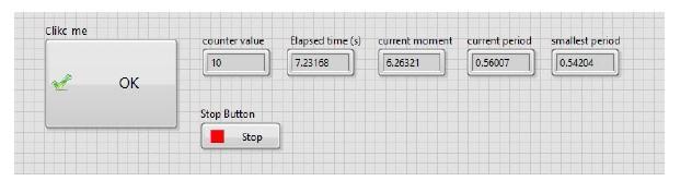
Solution The Peak Detector VI takes an array of points representing a signal and finds the locations, amplitudes, and second derivatives of any peaks or valleys in the signal. Routing a Signal to Counter n Source Each counter has independent input selectors for the Counter n Source signal. Any of the following signals can be routed to the I am having real troubles with a seemingly easy task in LabView. So the task is, that you have some kind of a counter which goes from 0 to 60 and a push button. If you press
- Invesco S – Invesco Technology S&P US Select Sector ETF
- Invasiveの日本語訳 _ 【Invasive】の例文や意味・使い方
- Internist In Berlin Bezirk Pankow
- Installation Officielle Du Nouveau Cdca Alsace
- Install Symfony Php Framework On Debian 12
- Integrated Telecom Company : Integrated Telecom Company
- Intro Letter To Client – An Open Letter to Clients in Therapy
- International Iso Standard 1496-4
- Intermittents Du Spectacle : Ce Qu’Il Faut Déclarer
- Install Onedrive Using Group Policy And Powershell